
Camera Calibration based on Bicubic Splines

|
| Camera Calibration based on Bicubic Splines |
|
Assume the camera is imaging a certain work area. Also assume the work area is a plane.
Assume an application where a robotic manipulator has to pick up objects placed on the work area, or it has to do some job over certain positions on the work area (ex: screwing). Assume this objects or positions are not in fixed positions on the work area, but they have to be detected by computer vision. Assume also the camera is fixed over the work area, that is, it is not an onboard camera mounted on the robotic manipulator.
A computer vision application detects the positions of interest, but these positions are detected in image coordinates, that is, row and column.
It appears the problem of converting this row/column to real world positions in milimeters, in a certain coordinate frame. This can be done if the camera is calibrated. Furthermore, it is important that the calibration method deals with small camera motion and small distorsions of the image due to the optics.
Here we present a calibration method that solves the problem. It has been tested on industrial machines to pick up small objects in motion, of sizes around 10mm, with accuracy of 1mm in a work area of about 600mm. The image resolution (pixel size) in this test machines was around 0.4 mm per pixel.
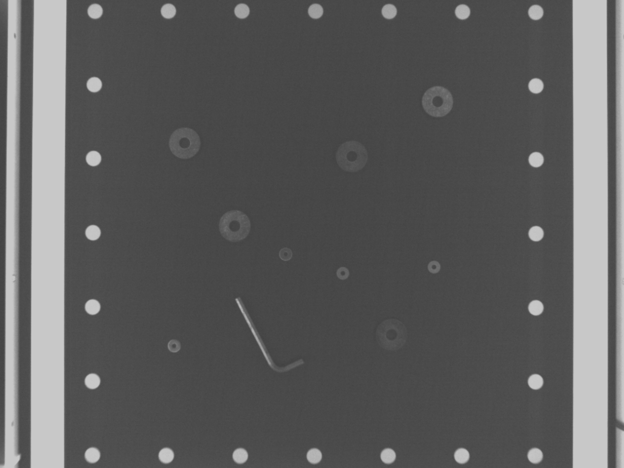
The perform the calibration, several calibration marks are detected. These marks are placed at known positions in the work area, and define a coordinate frame, X and Y axes. We have used the centers of white circles as the calibration marks. The calibration is done calling a library function and passing the set of calibration marks. Once the calibration is done, calling another library function one can transform a pixel in image coordinates (row and column) to a position (X,Y) in milimeters in the world reference frame defined by the calibration marks.
The calibration is performed at every image taken, so small displacements of the camera, or displacements of the work area, do not affect the calibration.
The main application of this calibration method is that a robotic manipulator can access any position in the work area. This work area is inside the calibration marks.
Information on OpenCV can be found at:
And the OpenCV distribution used in the demo program is: Bibliography on OpenCV:The demonstration program, source code and Windows executable, is:
As an example, a calibration template is available here for download. It has been prepared with the xfig program (a linux/unix utility). But other drawing programs can be used.
The library is in the form of a static library SplinesCalibration.lib and a dll SplinesCalibration.dll
Please see pictures and a a video of the system working on an industrial mechine at www.init.uji.es
For any inquiries about the splines-based camera calibration library, how to obtain it and use it, please contact.